Overview

The purpose of this project was to construct a circuit using logic circuits that displayed my birth date, 02 10 02, on 7-segment displays. We had to use common cathode displays and limited types of logic chips. We had to simplify our expressions using Karnaugh-Mapping. (K-Mapping)
Truth Table
The purpose of the truth table was to easily categorize the outputs of the circuit so that they can be easily separated and worked on through k-mapping.


MultiSim
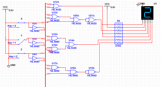
In my MultiSim design, I used a bus to simplify the wiring. A total of 13 logic gates were used to complete this circuit. The types of gates are listed below. A Common Cathode 7-segment display was used along with 7 210 Ohm resistors. Because 3 pf my logic expressions were identical, I was able to use 1 Circuit and wire it into 3 outputs. One of my segments was always on so I wired it directly to power, eliminating the use for another circuit. A total of 3 separate logic-circuits were used; 1 AOI, 1 NOR, and 1 NAND.
Bill of Materials
|
|
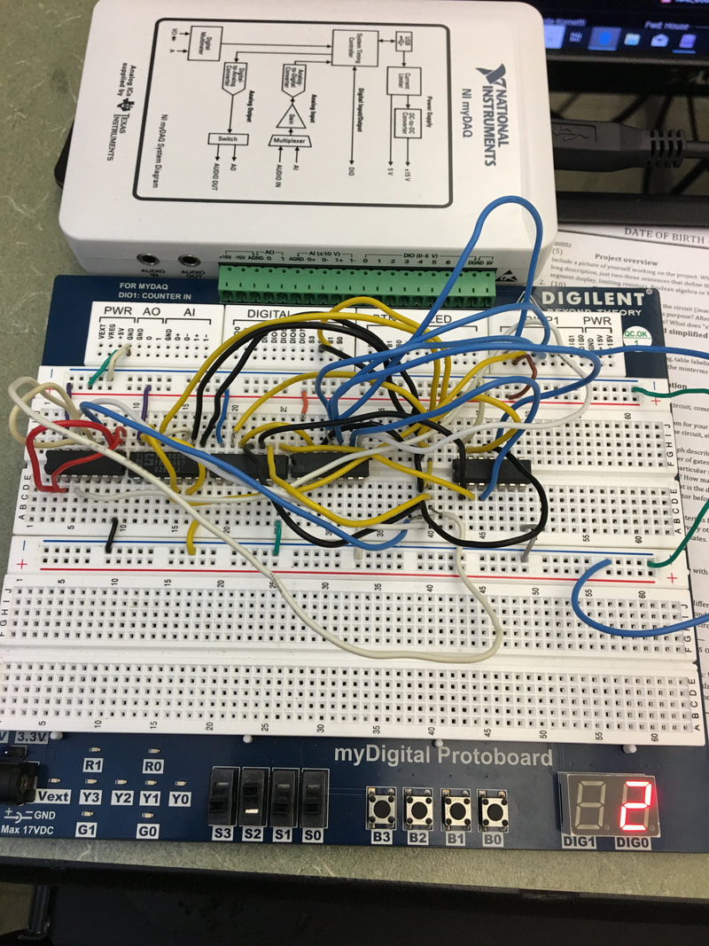
Bread-boarding
|

|
Considering that this was my second attempt breadboarding a complex circuit, it was relatively easy. I had no problems wiring my circuit, only loose chips that needed to be held in place. This seemed to be a lasting problem that no amount of skill/practice can prevent. I enjoy breadboarding and look forward to our next project.
